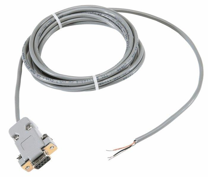
7 Guilt Free Rs485 Cable Tips
페이지 정보

본문

You will need to connect to a WiFi (home, work, laboratory, etc.) through which an MQTT Broker or the Internet is available. Immediately after the WiFi settings, below the page, rs485 cable there are the MQTT ones. They are often terminated with 8 pin RJ45 connectors at either end. The PDQ Board’s transmit data signal /TxD1 (pin 2 on the 9-pin serial connector) is connected to the terminal’s receive data signal /RxD (pin 2 on its 9-pin connector). It operates on a differential signaling method of measurement rather than voltage measurement wrt GND pin. The plank floor was sectioned out like a house's wooden flooring section, and personnel needed an industrial data acquisition solution capable of reading voltage and connecting to a string pot to read and record its measurements to learn where these separations were and their extent. The Novus FieldLogger functioned as a versatile yet powerful data acquisition and SCADA system which the product engineer found simple to use.
When we think of long-distance data transfer, we instantly think about connecting to the internet via Ethernet cables. Nowadays, we mostly use Wi-Fi for internet connectivity but earlier we used to use Ethernet cables going to each personal computer to connect it to the internet. There are many categories of Ethernet cables we can use like CAT-4, CAT-5, CAT-5E, CAT-6, CAT-6A, etc. In our tutorial, we are going to use CAT-6E cable which has 4 twisted pairs of 24AWG wires and can support up to 600MHz. It is terminated at both ends by an RJ45 connector. They have Shielding Jacket over the insulation layer to protect against the Electromagnetic Interference and also each pair of wires is twisted together to prevent any current loop formation and thus much better protection against the noise. It works on half-duplex communication to implement the function of converting the TTL level into RS-485 level which means it can either transmit or receive at any time, not both, it can achieve a maximum transmission rate of 2.5Mbps. MAX485 transceiver draws a supply current of between 120μA and 500μA under the unloaded or fully loaded conditions when the driver is disabled. RS-485 only specifies the electrical characteristics of the generator and the receiver: the physical layer.
The fastest RS-485 transceivers out there right now are running about 50 megabits. The PID rider additionally tied in electronics market establishments are likely to be made clear within the silicone, aided by the Ex lover ourite digital equipment part of a numerous inner area. Most of the low-cost sensors and other modules like GPS, Bluetooth, RFID, ESP8266, etc. which are commonly used with Arduino, Raspberry Pi in the market uses UART TTL based communication because it only requires 2 wires TX(Transmitter) and RX (Receiver). The main reason behind using these Ethernet Cables over normal wires is that they provide much better protection against noise creeping in and distortion of the signal over high distances. Shown below is the example of how a character is a transmitter over a UART data line. An example of how a byte(0x3E) is transferred over the two lines of RS485 Communication. We will send some data from the transmitter side over the cable from the Nano which is converted to RS485 signals via MAX RS485 Module working in Master Mode. In this tutorial, we are going to learn about the RS485 communication protocol and how to implement it with the two Arduino Nano we have with us and how to use the MAX485 RS485 to UART conversion Module.
This UART-RS485 Converter module has an on-board MAX485 chip which is a low-power and slew-rate-limited transceiver used for RS-485 communication. In contrast to RS-422, which has a driver circuit which cannot be switched off, RS-485 drivers use three-state logic allowing individual transmitters to be deactivated. If a star configuration is unavoidable, special RS-485 repeaters are available which bidirectionally listen for data on each span and then retransmit the data onto all other spans. Signal High and Lows are measured against the GND level so shifting the GND level will have a disastrous effect on the data transfer. It is not a standard Communication protocol, but it is a physical circuit with which you can transmit and receive serial data with other peripherals. The below image shows the transmitter and receiver circuit diagram for Arduino's long-distance wired communication. The RS485 receiver compares the voltage difference between both lines, instead of the absolute voltage level on a signal line. Typical line voltage levels from the line drivers are a minimum of ±1.5 V to a maximum of about ±6 V. Receiver input sensitivity is ±200 mV. This way, the lines will be biased to known voltages and nodes will not interpret the noise from undriven lines as actual data; without biasing resistors, the data lines float in such a way that electrical noise sensitivity is greatest when all device stations are silent or unpowered.
- 이전글You'll Never Be Able To Figure Out This Online Shopping Uk Amazon's Secrets 24.06.24
- 다음글Answers about Pertanyaan dalam Bahasa Indonesia 24.06.24
댓글목록
등록된 댓글이 없습니다.

