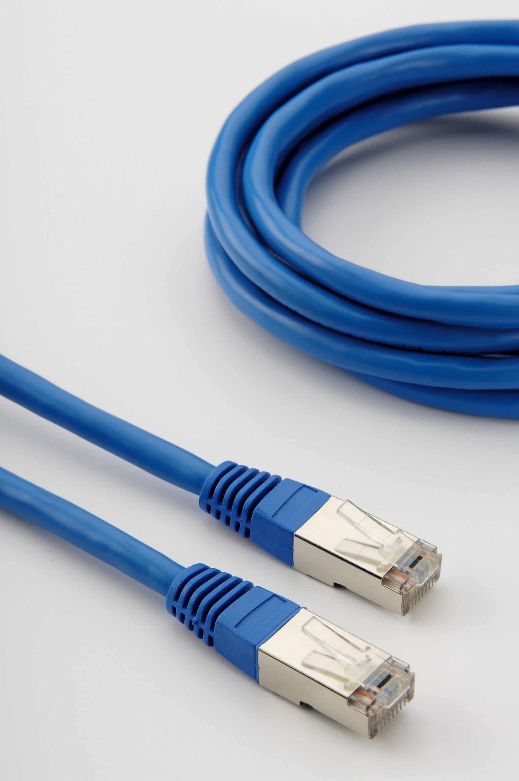
Rs485 Cable For Newcomers and everybody Else
페이지 정보

본문
RS-485 does not define a communication protocol; merely an electrical interface. It does not specify or recommend any communications protocol; Other standards define the protocols for communication over an RS-485 link. The EIA once labeled all its standards with the prefix "RS" (Recommended Standard), but the EIA-TIA officially replaced "RS" with "EIA/TIA" to help identify the origin of its standards. The EIA has officially disbanded and the standard is now maintained by the TIA as TIA-485, but engineers and applications guides continue to use the RS-485 designation. In a computer system, SCSI-2 and SCSI-3 may use this specification to implement the physical layer for data transmission between a controller and a disk drive. RS-485 signals are used in a wide range of computer and automation systems. 12 V, i.e. ±7 V on top of the 0-5 V signal range. The normal way to implement this is with a two wire system with differential signal levels. Section 4 defines the electrical characteristics of the generator (transmitter or driver), receiver, transceiver, and system. This section also defines the logic states 1 (off) and 0 (on), by the polarity between A and B terminals. 32 P-channel MOSFET board with screw terminals - when you need to Source current vs sink current.

The board is a little bigger in length now, 77mm across by 73mm, has each header pins brought out to a 3.5mm pitch screw terminal, and to a pin in the 12x20 protoboard area. Header for offboard FTDI Module (can be right angle or vertical), "L" LED at the edge of the board. Fits all Mega board variants: Mega, MegaADK, Due, Ethermega, Etherdue. Board with mostly thru-hole components (USB PTC fuse, 2 voltage regulators). These characteristics include: definition of a unit load, voltage ranges, open-circuit voltages, thresholds, and transient tolerance. Because a mark (logic 1) condition is traditionally represented (e.g. in RS-232) with a negative voltage and space (logic 0) represented with a positive one, A may be considered the non-inverting signal and B as inverting. Although many applications use RS-485 signal levels, the speed, format, and protocol of the data transmission are not specified by RS-485. In contrast to RS-422, which has a driver circuit which cannot be switched off, RS-485 drivers use three-state logic allowing individual transmitters to be deactivated. For an off, mark or logic 1 state, the driver's A terminal is negative relative to the B terminal. For an on, space or logic 0 state, the driver's A terminal is positive relative to the B terminal.
Barrel jack or screw terminal options for providing coil power & LED. Extra 3.3V/Gnd screw terminal added along with 4 more 5V/Gnd screw terminals. Board lengthened at the power connector end for additional screw down holes. The thru hole transistors went obsolete, so the board has been converted to all SMD except for the 74HC595s and the screw terminals. Contact me for pricing, PVT212 vs PVT312 and female vs screw terminals make a big difference. Or, lower capability (and cost) PVT312 with 3 ohm output resistance for 390mA current switching can be used. Easy to use - just shift in 4 bytes, a 1 turns an output on to sink current. RS-485 standard conformant drivers provide a differential output of a minimum 1.5 V across a 54-Ω load, whereas standard conformant receivers detect a differential input down to 200 mV. The termination also includes pull up and pull down resistors to establish fail-safe bias for each data wire for the case when the lines are not being driven by any device. The standard does not discuss cable shielding but makes some recommendations on preferred methods of interconnecting the signal reference common and equipment case grounds.
PC environment. 8P8C modular connectors are used in this case. The two values provide a sufficient margin for a reliable data transmission even under severe signal degradation across the cable and connectors. Star and ring topologies are not recommended because of signal reflections or excessively low or high termination impedance. Ideally, the two ends of the cable will have a termination resistor connected across the two wires. The value of each termination resistor should be equal to the cable characteristic impedance (typically, 120 ohms for twisted pairs). Without termination resistors, rs485 cable signal reflections off the unterminated end of the cable can cause data corruption. Interoperability of even similar devices from different manufacturers is not assured by compliance with the signal levels alone. This connection may be used to limit the common-mode signal that can be impressed on the receiver inputs. Circuits may be terminated on screw terminals, D-subminiature connectors, or other types of connectors. It may be used to control video surveillance systems or to interconnect security control panels and devices such as access control card readers. SD card with 74HC4050 SPI buffering, MAX3232 for RS232 on Serial 2, battery bacled DS1307 with 32.786 KHz crystal. Depends what you mean by a serial cable - Fibre, Ethernet, RS232, RS485, RS422, USB, HDMI, SMPTE292 are all examples of serial communications media.
- 이전글New panel for steam workshop downloader 24.06.20
- 다음글sm카지노하는곳⥵【bb4545.CΟ Μ】⥵헤라카지노 24.06.20
댓글목록
등록된 댓글이 없습니다.

